Introduction
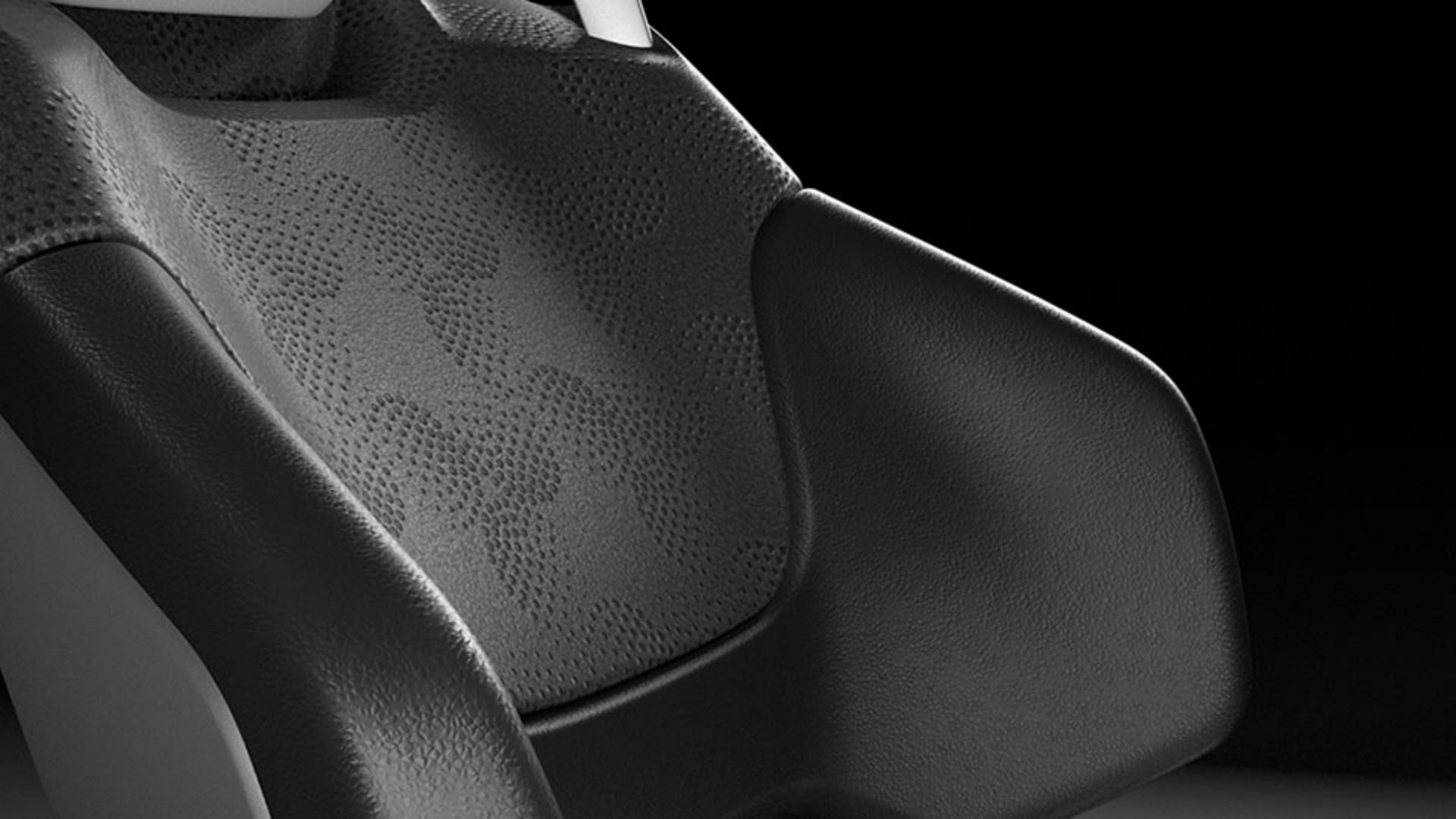
Hi, in this video you’ll be building a completely dynamic, artificial leather material from scratch, using Substance 3D Designer.
You’ll see how to create a few base leather grain patterns, how to go from a simple grain pattern to an actual material, and how to combine your grain with custom geometric patterns.
You’ll also see how to prepare for, and use your material in other 3D applications.
For this video we’ll assume you already have some basic knowledge of Substance 3D Designer; if not, don’t worry, we have introduction videos for you to watch first.
If that sounds good, let’s go ahead and get started.
On Designer’s Welcome screen, click on New Substance Graph.
Setting up the project and material graph
In the New Graph dialog, pick “Metallic Roughness” in the templates list to the left.
Because you’re making a full material, this template gives you a good base to start from.
All that’s left is to name your graph “Artificial Leather” and click OK.
With our new graph opened, you see the template’s nodes result in a flat gray material in the 3D view.
First, let’s create your base leather grain.
Creating the first leather grain pattern
Hit spacebar, and search for “reaction”, then add the Reaction Diffusion Fast node by clicking it.
This interesting node creates organic-looking patterns by “growing” shapes from white input points, similar to how real patterns are formed in nature.
It doesn’t do anything by default because you need to connect a “seed” input to it.
Ideally these are some random white spots, so open the node menu again, and search for “Spots”.
Gaussian Spots 1 is a good choice in this case, so add it, and connect it to the Reaction Diffusion input.
If you double click the Reaction node, you can preview the pattern, and play with the radius slider.
A large radius gives bigger patterns with large shapes, a smaller radius gives finer detail, so let’s settle on 0.4 for now.
To see this on your material, connect the Reaction output to the already existing Normal map node.
Right away you see a result, which looks very sharp and not very believable. you need to soften and inflate your shapes a bit.
Softening is easy, select the wire you just created, hit spacebar and add a Blur HQ Grayscale node.
Blur starts off too strong, you want to set the blur Intensity down to about 0.6, where the base shapes just start to fade into each other.
This already looks better in 3D, but still not great.
Select the last wire again, and this time add a Slope Blur Grayscale node.
To get this to work, you need to reconnect the same connection to both inputs of the slope blur, you can use Ctrl-Drag on the top input slot, to duplicate it to the bottom one.
The Slope Blur’s intensity is very strong, it needs to be set to the absolute minimum.
Hold down Shift, and move the slider to 0, then bump it a single notch above 0 to 0.01.
Your grain looks about right now, with inflated, organic shapes.
You’ve just created your first base grain, but a leather material is more than a simple grain hooked up to the normalmap.
Next, you’re going to set up the other channels of the material
Building material channels and refining realism
to make this a believable leather material.
Select the 4 nodes you just added and move them more towards the left to free up some space.
Let’s start with the basecolor.
Take the uniform color node connected to the top basecolor output, move it to the left, and change its color property to something more leather-like, like dark gray.
Then, select the orange wire, and insert a Blend node.
This common node allows you to mix two inputs together.
Take your Slope blur output from our grain and connect it to the top connection of that Blend, labeled “foreground”.
The wire turns dotted red, and nothing happens.
This is because you’re mixing color and grayscale nodes, and you need to convert the grayscale grain to color.
Select the red error wire, and search for “gradient map”, once added, this node converts grayscale to color, and our result becomes visible.
All that’s left is to change the blend mode of the node to AddSub and set the opacity to 0.1, to get a subtle effect.
Let’s do the same thing for roughness!
Create a Blend between the roughness output and the connected solid color.
Connect the grain to the foreground of that Blend and set it to the Overlay mode.
If you look closely, you’ll see it’s the opposite of what we want: in between your organic shapes, you’re getting shinier material, while you want it to be duller.
To solve this, select the wire you connected to the foreground, and add an Invert Grayscale node.
This inverts the grain’s effect on roughness and gives more depth to our material.
Your roughness still looks a bit shiny, so select the grayscale value we started from and tweak until it looks right.
Before we move on, let’s check on the Normal node, and tweak the intensity a bit.
Reducing it below 0.5 looks a bit more subtle and feels more like leather grain.
The scale seems a bit too large, so if you select the grains slope blur, add another node by searching for “safe transform”.
This node let’s you safely repeat a pattern, so with a tiling of 2 and a bit more tweaking of the normals, things look right.
You’ve just made a proper, full leather material.
You did that by creating a base grain as a grayscale chain of nodes, and then using that same grain to affect the material channels in different ways.
You’ve only got one grain type right now, so let’s build a second one.
Because of the way you built things, it should be possible to swap the grain out easily.
The next grain is a bit more complex, but as you’re probably getting the hang of it, we’ll move a bit faster.
This one is based on a Voronoi noise, so go ahead and use Spacebar to add one.
Go into the properties; set Scale to 64, Distortion intensity to 0.25, Rounded Curve to 0.7, and Style to F1/F2.
This gives us a good base noise shape.
Next, add a Levels node and slide the top middle slider halfway to the left, for some more brightness.
Just like your last grain, the next node is a Blur HQ Grayscale, where you make sure to set the intensity to 0.3 to soften it up.
You’ve made your big shapes, now add a Blend node to mix in some finer detail, making sure the Blur is connected to the middle, background slot.
Before you go further, let’s first make sure you can see what you’re doing in 3D.
Shift-drag the root connection from our previous grain’s Slope Blur, and move them to this Blend.
The entire material updates to use the new grain.
Then, create another Voronoi node, but this time it’s the Voronoi Fractal version because it has a much softer, grainier look.
Connect it to the top, foreground slot of the blend.
Tweak that second Voronoi node’s Scale to 10, the Distortion Intensity to 0.1, the Distortion Scale to 40, and roughness to 0.85.
The Blend node isn’t doing much now, so we’ll change its mode to Multiply, and the Opacity to 0.5, which gives us a nice mix of small and Large details.
You’ve just built a second leather grain, using some familiar techniques like Blur, and new ones like mixing two noises at different scales.
So far you switch between the grains by dragging wires
Creating multiple grain types and using a switch
back and forth, but that’s not an ideal workflow.
You want to set up a nice Switch node to toggle between multiple options.
That node is Multi Switch grayscale.
It takes multiple inputs, and only outputs the input of your choice.
If you place it between our grains, but before the safe transform, you can hook everything up.
The safe transform is specifically placed after the switch because we want to tile all of our grains equally.
By default the multi switch has two inputs, but the Input Number slider lets you set how many inputs are available.
The Input Selection slider is the control that chooses which input becomes an output.
Take care, it’s not capped at your input number, so setting it too high will result in a black output.
So set the Input Number to 3, and get ready to create your third and final grain.
Your third grain is the most realistic one yet, based around the Triangle Grid Grayscale node.
Once you add this node, set the Color Output to Distance to Edge, for that leather-like cell look.
To make the cells smaller, set X and Y amount to 64.
The Cells get very dark because the distance calculation was set for large cells.
Find the Distance to Edge Thickness slider at the bottom, and change it to 0.005, to work with small cells.
The cells are very uniformly placed, and you can use a trick with a normal map to break this up.
To the left of the Triangle Grid, create a Gaussian Noise node.
You want some big noise, so reduce the scale of the Gaussian to 6.
Then you’ll hook it up to a new Normal node, which turns it into a normalmap.
The effect is very subtle, so crank up the Normal Intensity to 500, giving you a very strong result.
Plug that result into the middle, orange input of the Triangle Grid node.
Then find the Vector Map Displacement slider and increase it to make the grid shift and break up in interesting ways.
The next steps are similar to what you did for the other grains.
A Blur HQ node with a low value of 0.5 softens the triangle grid.
To break up the uniform look of each triangle, place a Slope Blur node next.
Instead of connecting the same input twice, add a new Gaussian Noise, that you set to a scale of 256, for tiny detail.
Connect the Gaussian to the bottom input of the Slope Blur, and then use the Shift key to slide the Slope Blur intensity to 0.01.
You can already plug this version of the grain into the multi switch to preview what it looks like.
It needs a bit more adjustment, so add a Levels node to add some more brightness, by sliding the top middle slider a bit to the left.
Finally, let’s insert another Blend node to mix in a new Voronoi Fractal.
Set the Blend Mode to overlay.
Then Our Voronoi Fractal needs to be smaller, at a scale of 48, and brighter, with a Rounded Curve of 0.5.
You’ve now built three types of grain, each time with a different approach, using noises, blurs and blending.
This gives you an extensive base to build upon.
Before you go further, let’s set up some controls for your base grains.
When you use this material in other applications, you want to be able to choose the grain type, change the basecolor, grain intensity, and the roughness.
This step is called “exposing”, and it involves finding the right parameter in your graph, and exposing it for external control.
Let’s do that first for our Basecolor.
Find the Uniform color node used for the basecolor output at the top, click the little dropdown menu to the right of the main color property, and click “Expose as new Graph input”.
In the Expose Dialog, you can set a descriptive name for the parameter, so let’s use “Basecolor” instead of output color.
Once a parameter is exposed, it becomes unavailable in the node, but you can always check on it by double clicking an empty graph area and scrolling to the Input Parameters section.
There you can make changes to already exposed parameters.
Let’s do another key setting: the Multi Switch that sets which of the 3 grain types to use.
On the Multi Switch node, we’ll expose the Input Selection.
Name it “Grain type”.
The default slider isn’t nice to use, so set the Type/Editor to Drop Down List, then click the plus at the bottom right to add 2 more items.
Then you need to set the list of options up, the first column is the internal number, these will be 1, 2 and 3, corresponding to our original slider.
The second column is the UI name, you can use anything descriptive here, such as Grain 1, Grain 2 and Grain 3.
Once that’s done, you’ve exposed a second parameter, and customized it.
Exposing even more parameters is the same process, so we won’t go into it too deeply anymore, just find the node, and expose the parameter.
We ended up with Roughness and Normal intensity exposed as well.
Your current graph is already useable in other applications, so if you want to test it out in Painter or Stager, right click the package, and pick Send To, to send it to another Substance application.
I’ve sent it to Stager as an example here and can assign and customize the material just as intended.
You’ve got your base leather material, but things get interesting
Adding custom patterns and exporting the material
once you can combine it with additional embossed patterns.
Here you can see a few of these vector patterns in illustrator, that we’d like to overlay onto the base leather.
You don’t need to get into Illustrator, but keep in mind your own patterns need to have square proportions, and need to tile or repeat seamlessly.
To test them out inside Designer, you can export them as either PNG bitmaps, or SVG vectors.
Once exported, drag and drop the exported files onto your package in Designer’s explorer window and pick “Link”, to reference these files on disk.
You don’t want to limit your options to just these 4 patterns, we’re using them as examples to test with.
Instead, let’s build a dynamic input system that lets you choose any custom pattern input.
To do that, add a new node called “Input Grayscale”.
Think of an input as an open slot, allowing you to insert any grayscale bitmap.
Under Attributes, name this Input “Extra Pattern”.
Next, drag a bitmap from the explorer, onto the input node to use it as a temporary, preview input.
The input slot stays dynamic, but you can build out the graph with one of our patterns.
By default it has no bitmap, and defaults to a black color.
Before we continue, let’s change one last key property on the Input node.
Set the Default value to white instead of black, so that when you have no input, a black color doesn’t affect our final result too much.
Next add a Safe Transform Grayscale node after your Extra Pattern Input node.
We can already expose the Tile parameter straight away, as we’ll likely want to change the tiling of the extra pattern compared to the base grain.
The input patterns are also pixel-sharp, with hard edges.
We want a soft, embossed look, so we can use the familiar Blur HQ Grayscale node after the Safe transform node.
Just set the intensity down to a subtle 0.8 value.
You’ll also want to expose it, to tweak later.
Now that you have the base setup for the extra pattern, let’s repeat what we did for the grain.
You’re going to mix the pattern in three times, once for Basecolor, once for Normal, once for Roughness.
Since you’re combining it with the grain, you can just splice it into each of those three connections.
Let’s try the basecolor first.
Create a new Blend node, and connect the main grain to the middle connection, then the extra pattern to the top one.
Set the blend mode to multiply to mix them, and move the opacity down slightly.
We can then use this blend node as the input for the blend that does the basecolor, replacing the previous grain connection.
The 3D preview updates to show the change but it’s looking fairly harsh.
We can reduce the opacity, but a new trick is to use a Highpass Grayscale node here.
The Highpass node is just like Photoshop’s filter, it reduces contrast detail.
Sliding the radius down to about 2.4 looks much better and less harsh.
Let’s move on to the Normals.
Create another Blend node, but swap around the order you connect the grain and extra pattern in.
The top, foreground slot of a Blend is controlled by the opacity, and you want the Extra pattern to be strong, and the grain to be light and subtle.
Hence, the grain should go in the top slot.
The Blend mode to use is AddSub, as it has a bit of a harsher contrast.
You need to drop down the opacity a lot, to about 0.15.
Connected to the normal node, it doesn’t look great yet.
The white parts of our pattern are clipping and look flat.
You can fix this by reducing the intensity of the pattern in the Blend.
Select the middle wire going to the Blend, and insert a Levels node.
Then grab the bottom, right arrow, and move it left.
This reduces the brightness of the white areas of your extra pattern, avoiding the clipping effect you see.
Your last Blend for the roughness is an easy one.
You can just duplicate the one you did for the Basecolor, using hotkey Ctrl+D.
Then hook up that duplicated Blend node to the Invert Grayscale we used for the roughness.
It’s looking a bit too strong, so tweaking the Blend’s opacity makes things more subtle.
You’ve just finished building out the material, by adding a dynamic input, and mixing that into all channels of the material.
At this point our material is as good as done.
You can make another pass to expose more parameters, but it’s not something we’ll go any deeper into.
You can then move on to exporting our final material.
If we right click our package, we can publish our material as SBSAR, a format that can be loaded in many applications such as Vred, Unreal Engine or Blender.
An SBSAR stays dynamic, so you can tweakyou’re your exposed parameters.
In this case we’ll stick with the easy Send-To workflow, to get your leather into Stager.
There, you can assign it to parts of the mesh.
There’s no extra pattern loaded, but once you find the Extra Pattern slot, you can even load the original Adobe illustrator file that we started from.
Stager lets you pick what Artboard to use, directly from the file.
Alternatively, you can just stick to PNG or SVG files.
And that covers creating a dynamic artificial leather material with Substance 3D Designer!