Introduction
When you think of 3D, you usually picture shapes that can be viewed from different angles.
Those shapes are called models, and they can be made of several components.
Geometry is the actual 3D form of the model.
It is the most basic invisible element, but a model also contains lights, shaders, and a rig with control handles.
Before you can start creating your own 3D geometry, it's important that you understand what it's made of.
Coordinates and axes in 3D space
The first thing you should know is that all objects and components in 3D have coordinates marking their exact location in the virtual space.
These coordinates are relative to a central origin, zero points that are in three dimensions, hence the term 3D.
Each dimension or axis is labeled with a letter X, Y, or Z.
There's no real standard between 3D applications on which axis represents what direction, but we usually consider the X and Y plane as a side view.
That means X is left and right, Y is up and down, and Z is front and back.
If a 3D application follows another convention, it usually means Y and Z are swapped.
These two conventions are called Y-up and Z-up.
Within these coordinates, geometry exists out of three simple elements vertices,
Understanding vertices, edges, and faces
edges, and faces.
Vertices, which is multiple for a single vertex, are small points.
Each vertex has its own set of coordinates in 3D space to define its position, vertices by themselves are not visible, so connections are drawn between them.
It is sort of three dimensional connect the dots.
These connections are called edges and are usually what you see when analyzing 3D geometry.
Where three points are connected, they form a triangle or tri four connected vertices form a quad, and anything over four is usually referred to as an N-gon.
Often all these types of faces are just called polygons.
Quads make for a more understandable geometry.
It's easier to read and understand geometry when not splitting into triangles, but faces don't have any volume or thickness that comes from connecting many together to create the illusion of volume.
So what you see as a 3D geometric object is a bunch of points connected as faces, resulting in a recognizable shape.
Surface normals and geometric smoothness
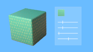
Another important component of 3D geometry is the surface normal.
Because faces have no thickness, normals determine which side of your geometry is the front or the back.
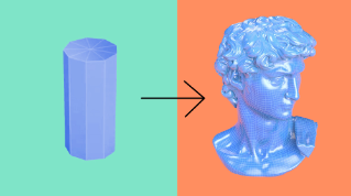
3D geometry's form made of flat polygons works well for simple angular objects, but it's not perfect for smooth, sloping objects unless there are lots and lots of faces, your objects will be faceted.
Normals are calculated automatically.
They can make simple geometry look better and give you more control.
Normals can make edges appear as a soft transition or as a hard sudden crease.
Large objects can easily contain thousands of vertices.
In some cases, there can even be millions of them.
How complex your model should be depends on many factors, but the most important factor will be what your geometry's intended use case is.
Your use case might be a 3D model for realistic visualization, or you might want a simple model intended for interaction on a simple mobile device.
Some 3D is not even intended for virtual on-screen usage.
Your 3D geometry could be a design for a product that will one day be manufactured.
Depending on the case you deal with, directly placing and interacting with vertices isn't always the easiest way to work.
And that's why there are two different ways geometry can be defined.
Geometry complexity and use cases
The first, called a mesh, is for virtual use cases where the exact arrangement of vertices, edges, and faces is most important.
Meshes have many advantages.
Existing hardware and code can work very fast and efficiently with it and they're easy to use for things like simulation, interaction, and modification.
They are the best choice for virtual display on screens, but they have some downsides.
They don't represent an actual volume and need to be very heavy to accurately represent curved surfaces.
The second way to define geometry is called CAD data
Mesh geometry versus CAD data
for computer aided design data, CAD is for when a precise, accurate way to define shapes is most important.
Shapes like cubes, cylinders, and sweeping surfaces can be created and combined without you dealing with vertices and faces.
Once your shapes are manufactured, they become paths and instructions for machines to print plastic, cut fabric or bend steel.
Think of it like pixels and vector shapes.
Just like 2D images made from pixels meshes are a clear, simple format, but there's always the concern of precision and resolution.
CAD data is like vectors, precise and accurate, which is required when your objects become real.
It's also good to know that a mesh can be easily exchanged between different 3D applications while CAD data won't always translate easily.
Due to their versatility, most applications work with meshes.
A few applications can convert CAD data into meshes for use elsewhere, but you won't be able to translate a mesh into CAD data.
None of these formats is better than the other.
They all have up and down sides depending on your use case.
Because meshes are so widely used, there's not one single file format and no one method to create them.
Now that you know about geometry, we'll dive into the methods for creating it in the next video.