Preparing a Substance Painter file for color 3D printing
In this tutorial you will learn how to
project surface details from texture maps onto a model, and how to prepare the Substance Painter file for 3D printing with color using Substance Painter, Blender, Netfabb and the Mimaki 3DUJ-553 Color printer.
It is presented to you by Jaime Martinez, a specialist of Additive Imaging and Integration at Mimaki.
The model used for this tutorial is Sea Monkey, one of the highly placed entries in the Meet MAT 2 contest, created by Adam Scott.
The model consists of two printed components, the body and the base.
Using a texture mapping workflow will reduce the number of steps required to get to a highly detailed model. This grants flexibility for modifications compared to a pure sculting workflow, and it's also efficient in terms of hardware resources. The process can be broken down into the following steps:
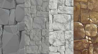
For color 3D printing, the Base Color, Normal and Displacement maps are required. Other maps, such as emissive, metal, roughness and ambient occlusion will be ignored by the slicer, because their purpose is to generate visual effects that often can’t be reproduced by the 3D printer.
The final printed model will be created from a plastic printing resin, with a matte finish. For this reason, 3D printing works best with models that are somewhat close to this appearance (or that can be modified to approach this appearance). This avoids color mismatching and unexpected differences between the digital render and the final printed parts.
For Sea Monkey we want to change the environment in order to flatten the color appearance, and to eliminate the glare of the metallic finish. Failure to do this will likely result in white patches on the final printed model, caused by reflected light on the 3D render.
In this case we’ve changed the default environment, from Tomoco Studio to Soft1LowContrast, in the Display settings.
The color appears flattened after changing the environment in this way. Note that this is only one possible solution at this stage; in some cases it might be preferable to play with the metallic values or delete them altogether. The same is true for the emissive maps and the emissive intensity.
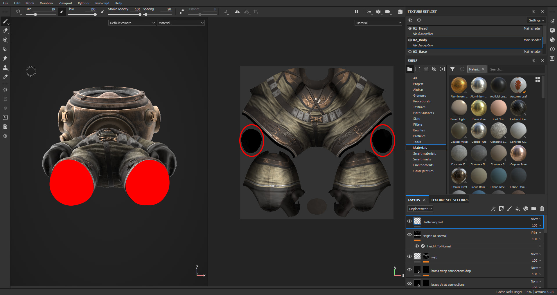
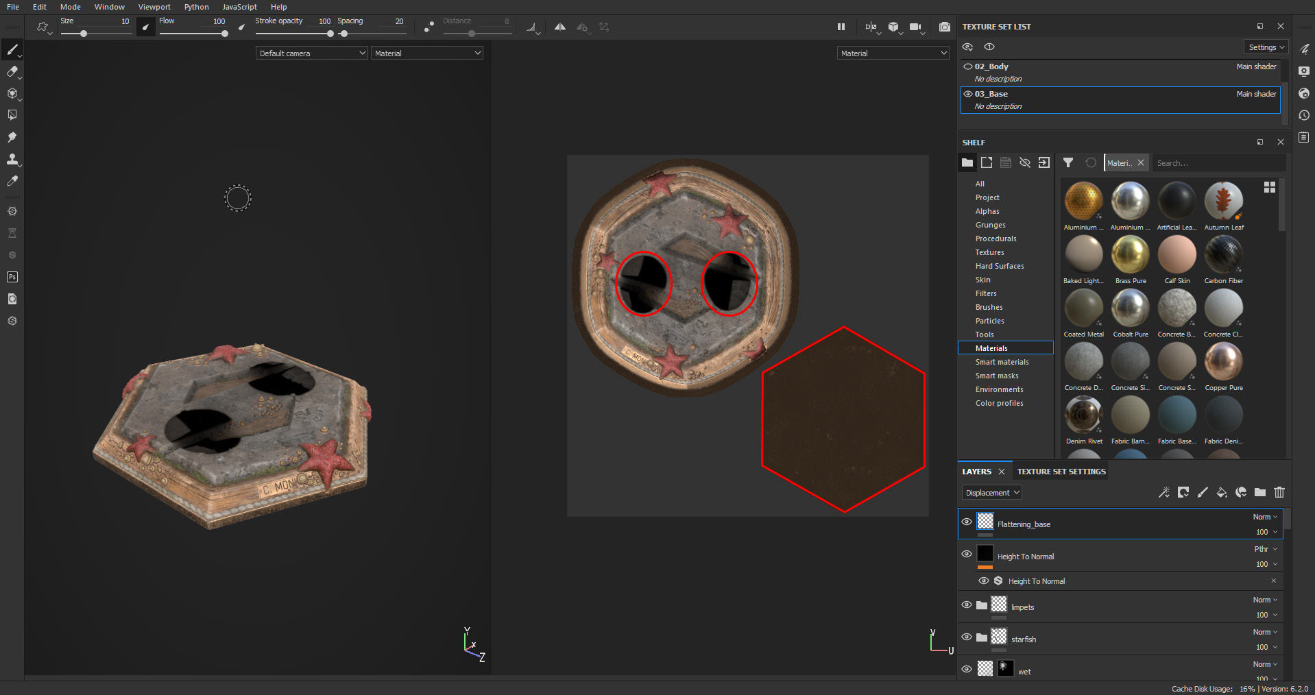
To make the figure stand properly on its base, create a paint layer for the displacement channel and use it to flatten the bottom of model’s feet.
Do the same for the contact surface on top of the base, where the base meets MAT’s feet, if applicable. Play with the opacity of the layer to try to keep some of the displacement and fine details.
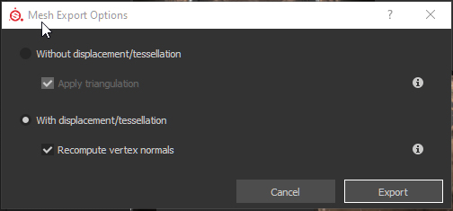
Substance Painter allows you to export a mesh projecting the details on its surface. This grants the potential to greatly reduce design time. First, go to File/Export Mesh; in the dialog box, check the ‘With displacement/tessellation’ option.
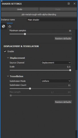
NOTE: As the level of subdivisions is controlled in the Shader settings, don’t go too crazy with the Subdivision count before exporting. In our case, for the Sea Monkey design, the subdivision count was set to 13, yielding a mesh with 14 million triangles. If a single mesh/material is selected to export, the designer can have more subdivisions where needed, and reduce triangle count in shells with simple surfaces.
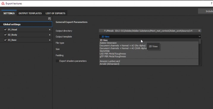
Now we need to export the base color texture. In this case, the 2D View Export is the most convenient option. If you aren’t sure what the output will look like you can use a regular paper printer to get a better idea of how the color of the texture will behave, as regular paper has an opaque matte finish and most printers have a CMYK ink configuration which will appear similar to your final 3D print.
This part of the tutorial will be about scaling and decimating the model to make it ready for the next steps.
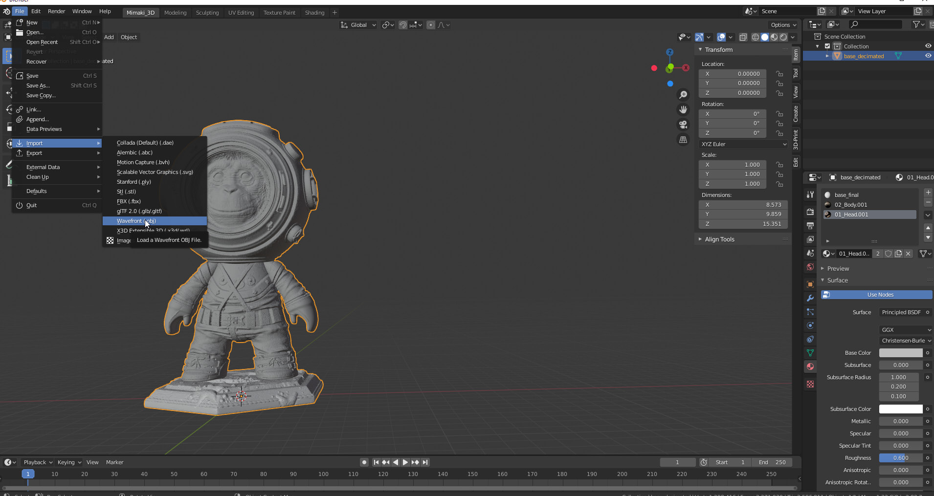
In Blender, import the mesh via File/Import Wavefront .obj
Then, use the Scale option (or S key) and scale the model to 203 mm (8 inches) tall.
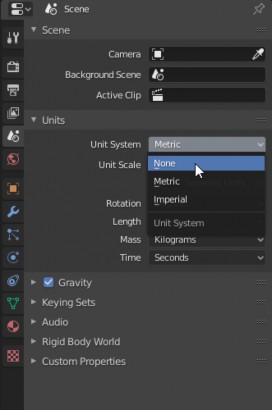
Although Blender is set to metric by default, which could be good for big scenes, this isn’t the most convenient setting for 3D printing. A lot of designers go to the Scene menu and set the units to ‘None’, where the base unit scale is set to 1, meaning that one unit in the scene is equal to a one millimeter in real life.
1 = 1mm
We recommend you use this setting too, as decimals and magnitudes are easier to handle, and most 3D printers are set to mm as well.
With the mesh selected, go to Object/Apply/Rotation and Scale to update the size change. Make sure you do this before exporting or making new transformations.
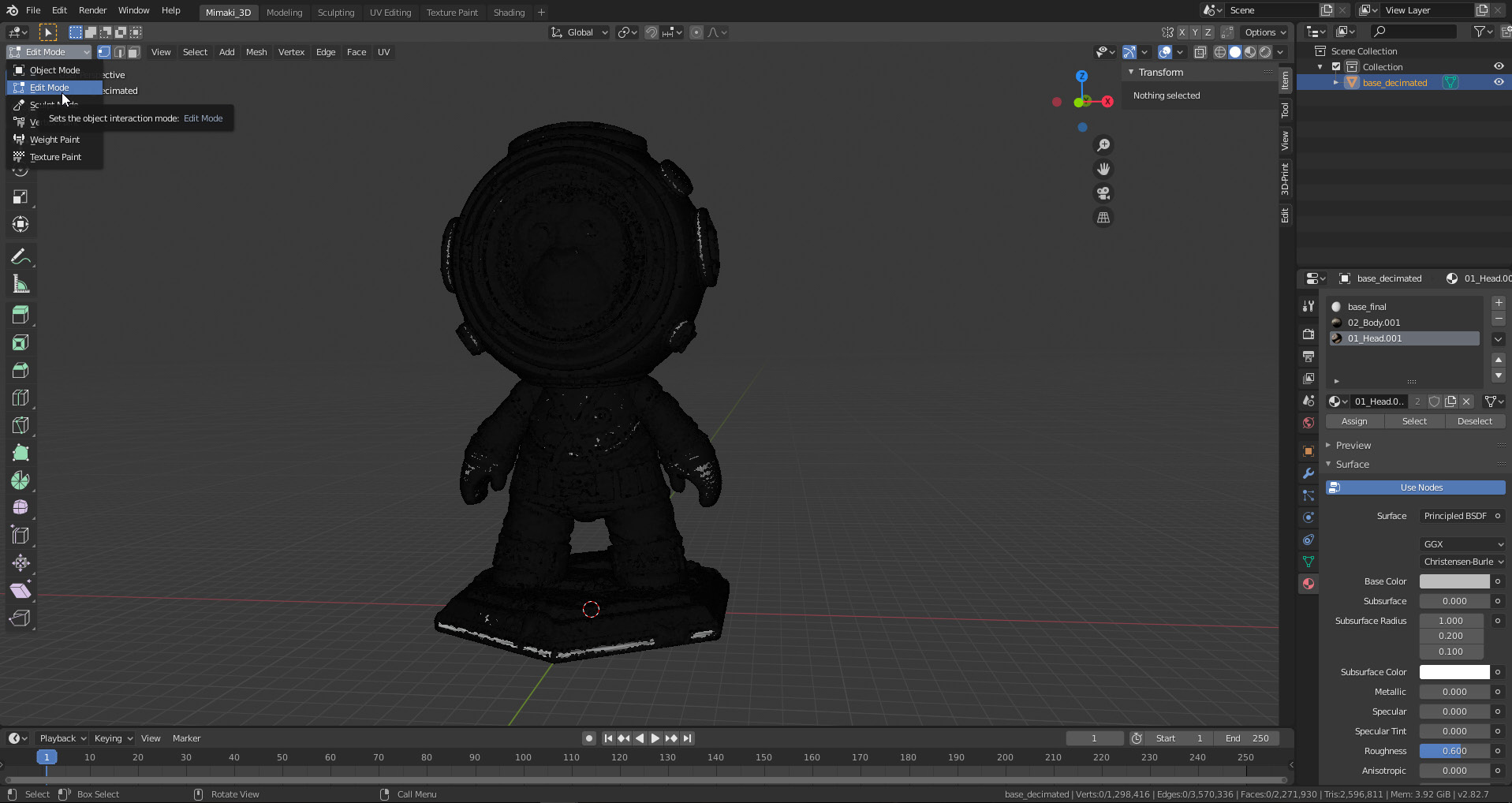
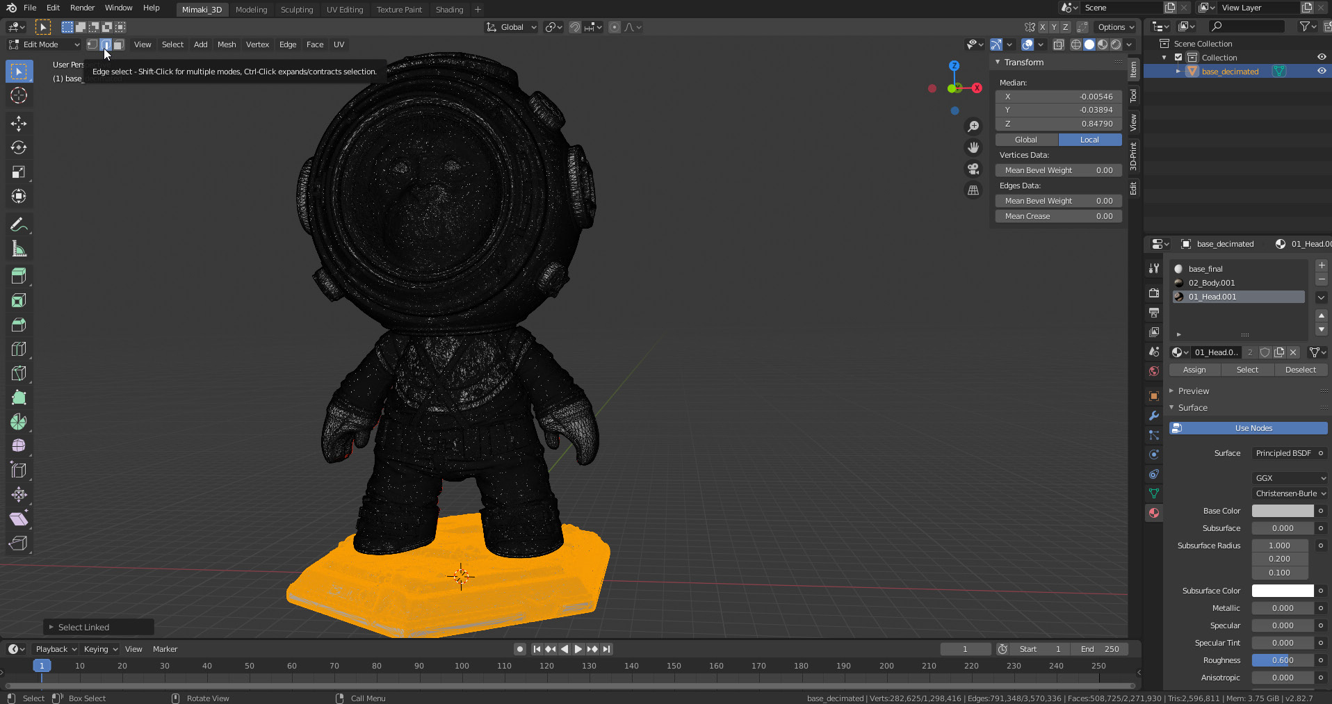
The mesh has 3 materials assigned in Substance: ‘head’, ‘body’, and ‘base’. At this step the base will be separated to be exported on its own. Select the mesh and Go to Edit mode (Tab key).
Click on the edge selection icon (2 key) or hover over the base and hit the L key; Blender will select all linked edges for the base.
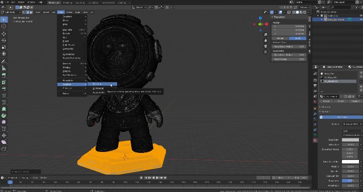
Go to Mesh/Separate/Selection (P key). This will separate the base from the body.
Return to Object mode with the Tab key.
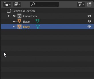
In Scene Collection, shells can be renamed to identify them easily. Collections can be created and managed like layers; it’s good practice to create duplicates before making any major modifications to the mesh.
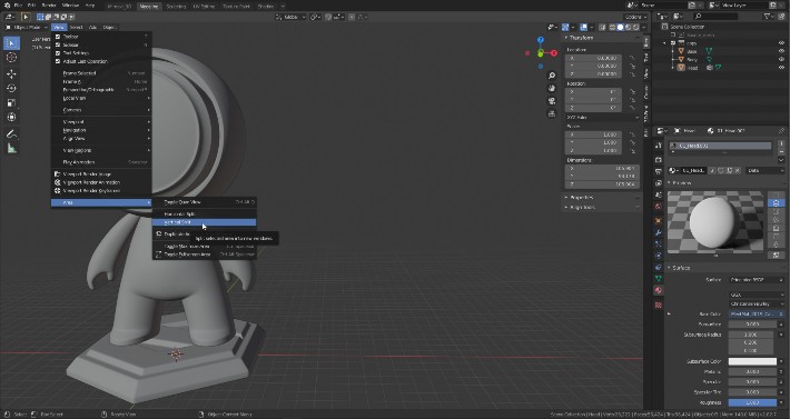
It’s always a personal choice to define a workspace. The user can choose between navigating the tabs to model, sculpt, UV edit, carry out shading, and so on. Make use of the keyboard shortcuts or use the classic area split to see changes in real time. To split the area, go to View/Area/Vertical split.
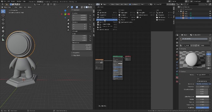
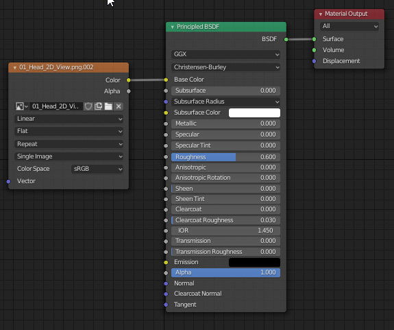
Click on the top left corner to open a dropdown menu and click in the shader. You’ll see something like the image below.
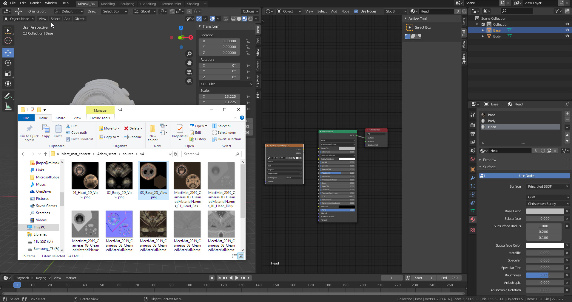
From your explorer locate the base color texture and then drag and drop it into the shader section. Blender will automatically create the image node.
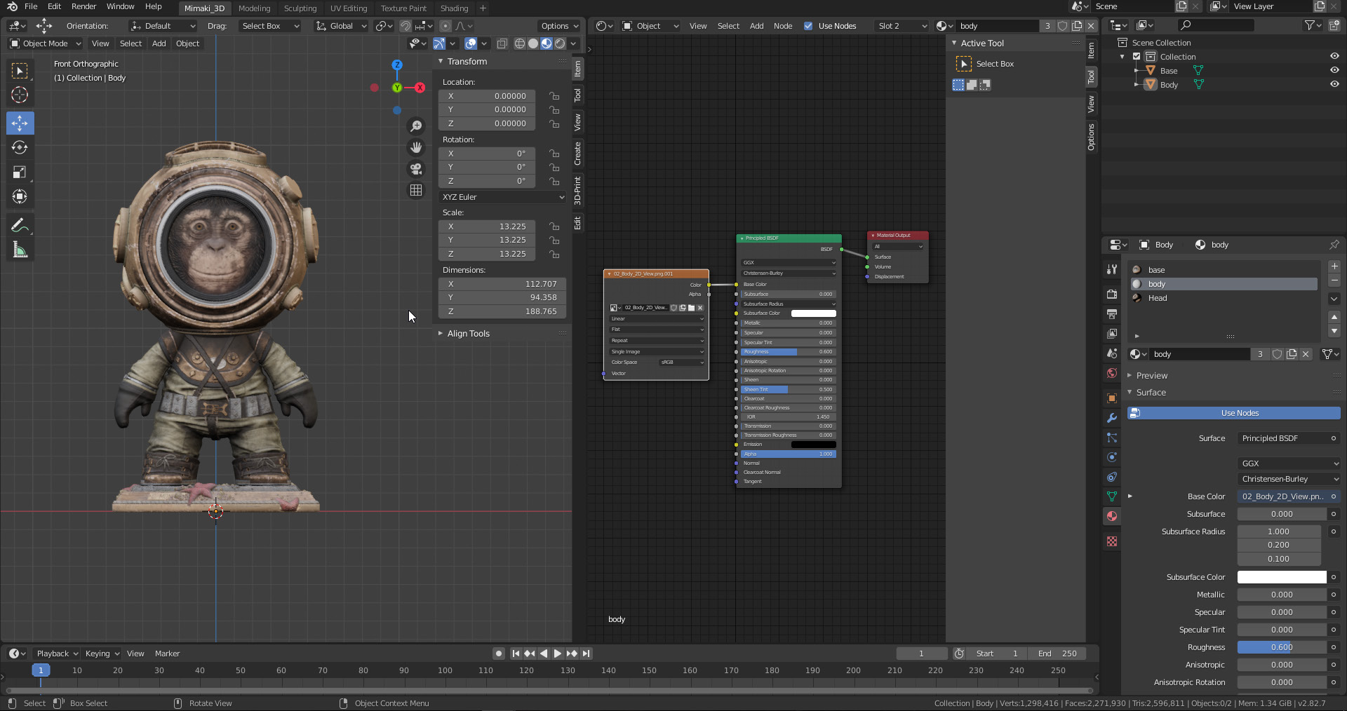
Connect the color socket from the Image node to the base color of the principled BSDF node. To visualize the color, click on the viewport shading icon on the top right corner of the 3D viewport (default).
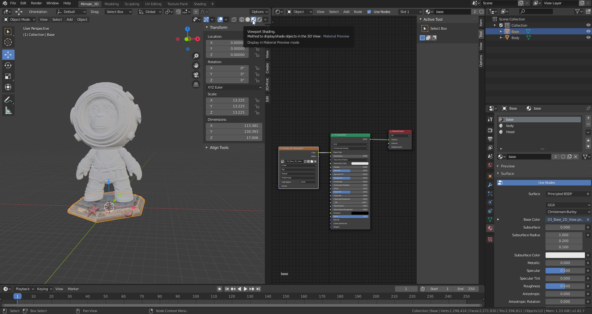
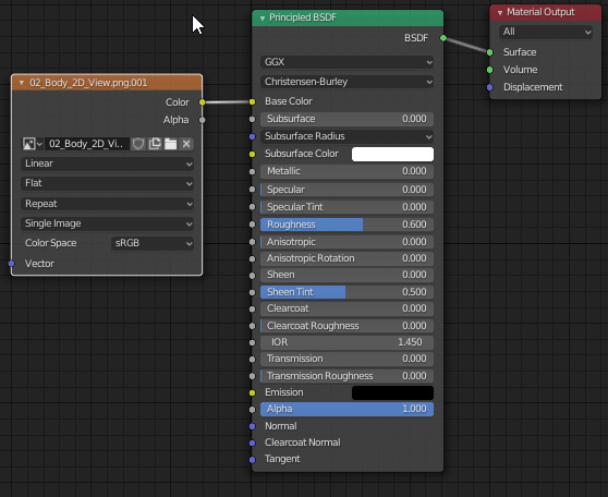
All materials can be visualized in the material section; clicking on the list element will update the related principled BSDF. This is handy for grouped shells like the head and body of Sea Monkey. Repeat the linking process for the materials.
Once done it should look like the image below.
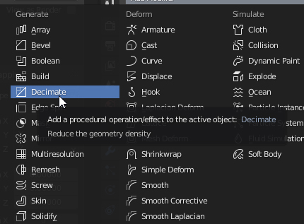
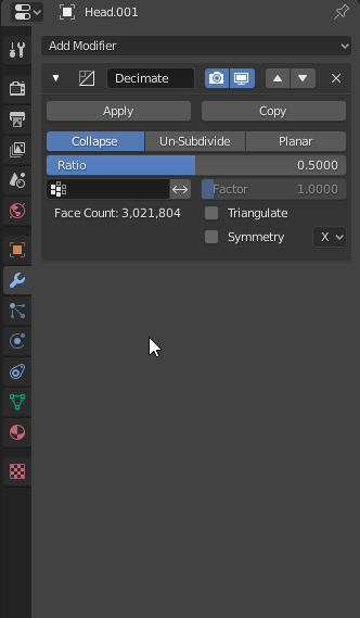
As the figure has a total of 14 million triangles now, it is necessary to reduce the amount of triangles with the decimation modifier.
This step is only to improve hardware performance, reduce the file size on the hard drive, and improve load times for the 3D printing slicer. Select the body, click the wrench icon for modifiers and locate the decimate option.
Decrease the geometry in 0.5 (50%) increments, apply and repeat until the number of triangles is manageable.
How much decimation do you need? It depends of the real-life scale and 3D printer resolution. For the Mimaki 3DUJ-553 this figure is about 0.3 mm for the smallest surface detail; anything more precise than this is overkill.
You could eyeball it by zooming the viewport to a scale close to real life and if you can see the detail keep it. Conversely, if it’s difficult to see, or if it seems that the printer may not be able to reproduce it, just let it go.
Decimate the base as well. In our case the final triangle count has been reduced from 14 million to 2 million.
To export the model with ease, the 3D-print Blender plugin is the fastest option.
The plugin will allow for file fixing as well – however, it’s strongly recommended that you carry out this step using a dedicated 3D file prepping software. When exporting files there is a chance of having issues with the surface of the mesh. This is commonly seen when exporting a quad- or Ngon-based mesh to the exchange formats that are triangle-based, like the .obj extension.
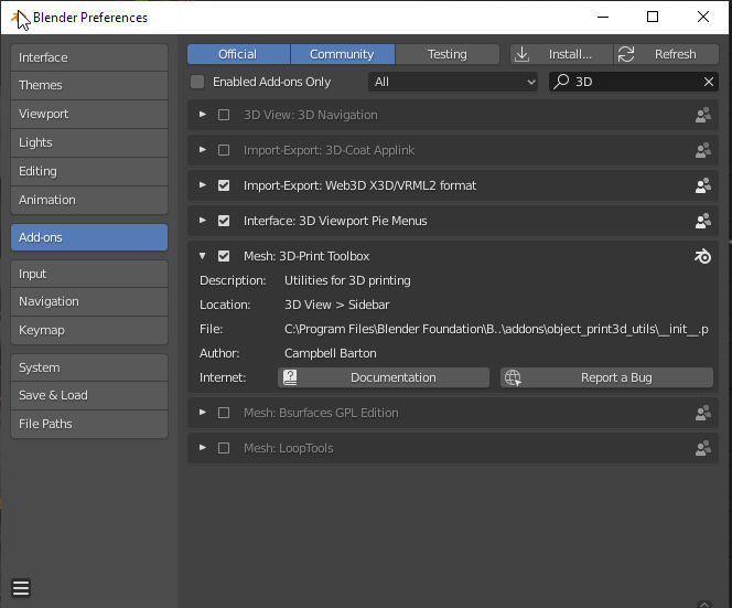
To activate the plugin go to Edit/Preferences
In the search bar, look for the 3D-print Toolbox and click the check box to activate it.
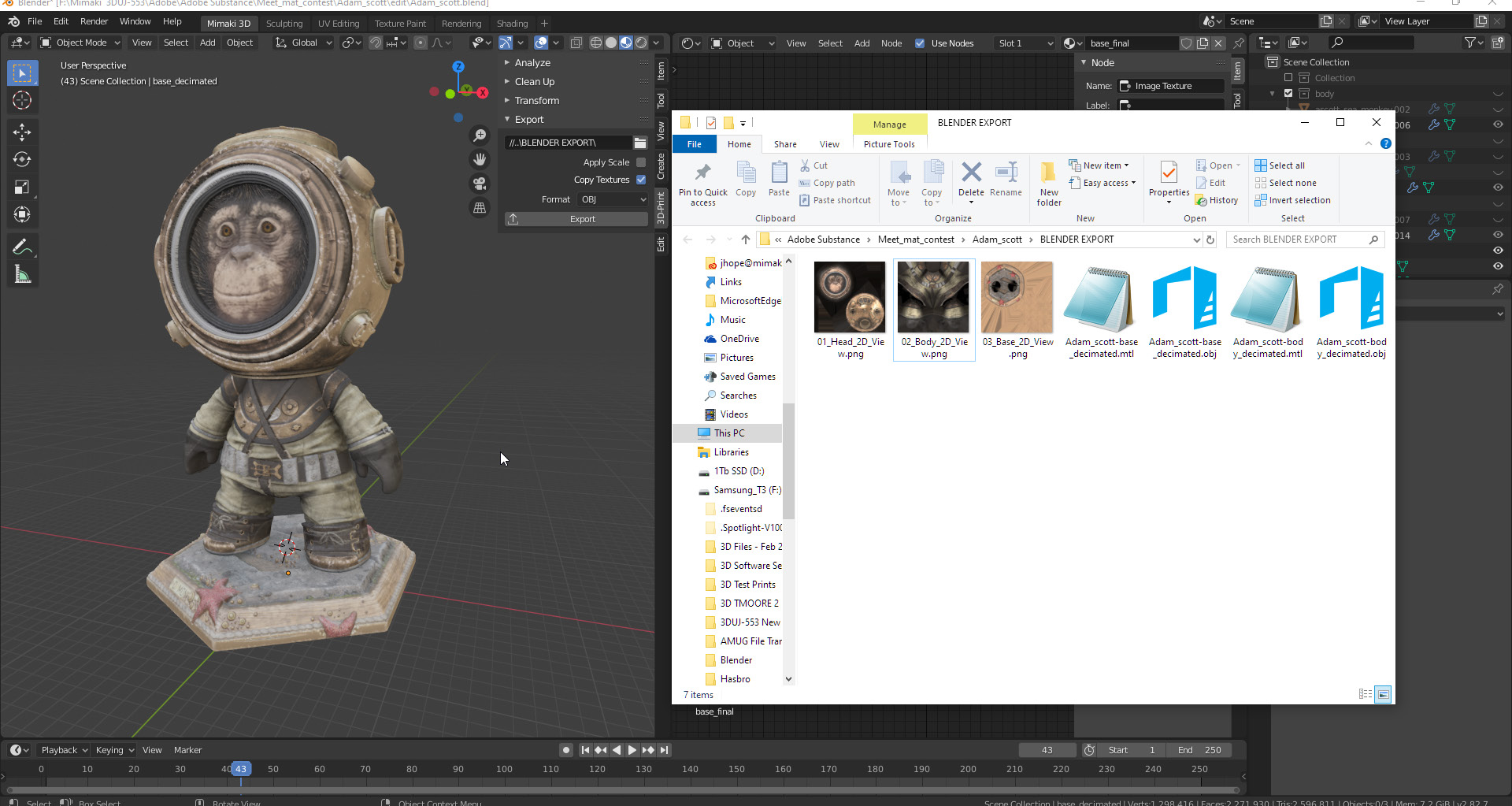
The 3D-Print Toolbox will appear to the side of the 3D viewport; click to expand it. Then look for the Export dropdown menu.
Define the save directory, and check ‘Apply Scale’ just in case you forgot to apply a scale modification. Check the ‘copy textures’ option; Blender will automatically create a copy of the base color linked in the Principled BSDF nodes.
Regarding the format, make sure that is set to OBJ as default is STL. A color supporting format is required. Select the head and the body to be exported in one file and click Export.
In the save directory, you should have three texture files and two .obj files and .mtl libraries. One is the head and body and the other is for the base.
Previously it was mentioned that exporting can cause issues in the mesh surface, but the resulting errors are less likely to happen if there is good modeling discipline.
A dedicated 3D file prep tool such as Netfabb will ensure that the mesh is watertight, also known as manifold or solid. It also allows you to arrange the parts and create printing layouts, which comes in handy when dealing with a higher volume of components for production.
For 3D printing as a whole, a valid mesh requires the following: - Inverted faces/triangles = 0 - Bad/non-defined edges = 0 - Surface holes = 0
Errors in faces and edges lead to printing failure, wasted material and time.
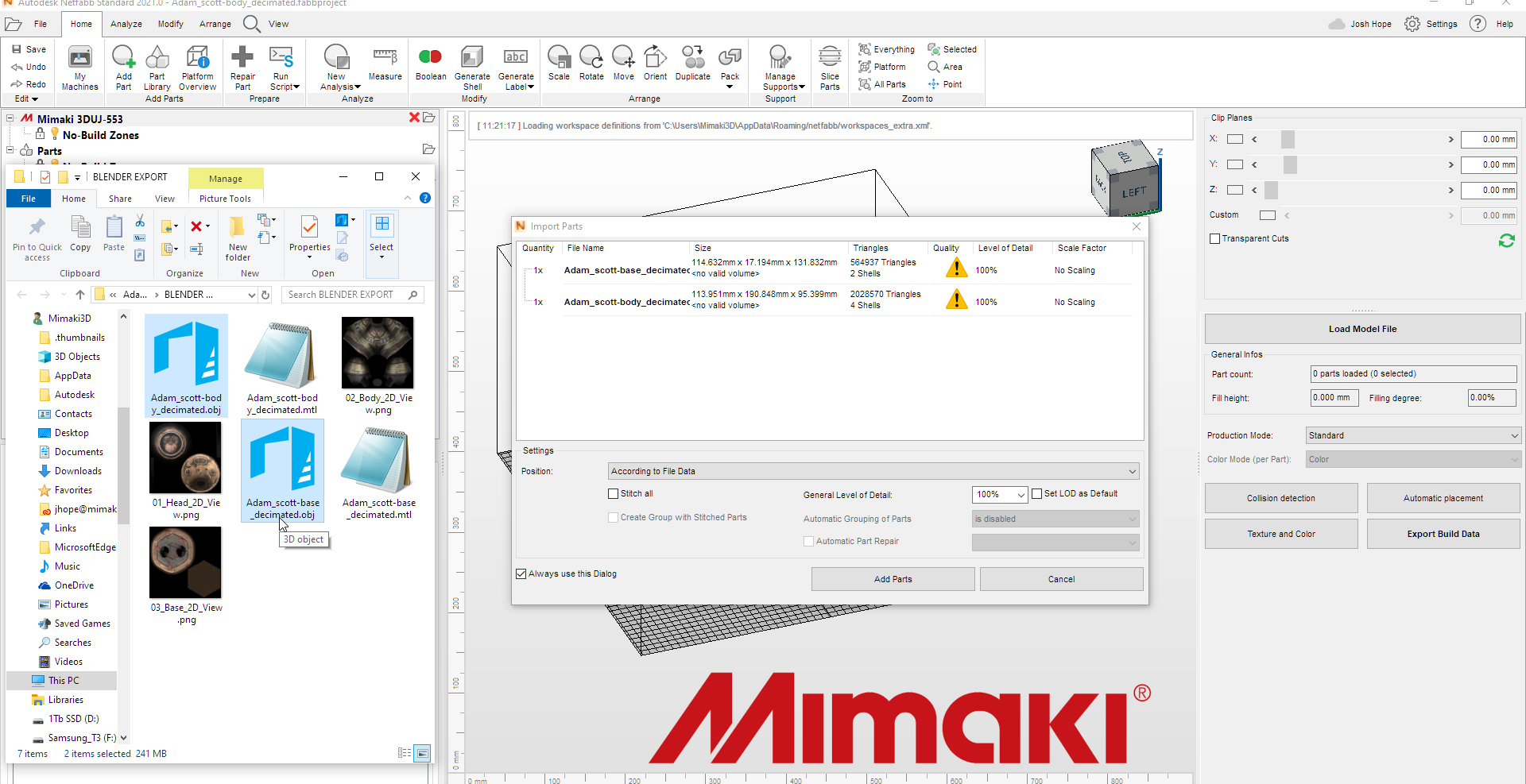
Locate the files in your explorer, select the mesh and drag and drop them into Netfabb’s interface.
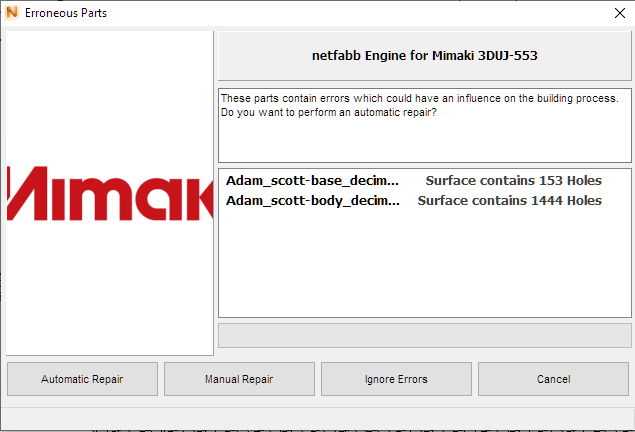
A dialog box will appear; a warning sign will be displayed on the files if a problematic issue is present on the mesh. In any case, click on ‘Add Parts’. Netfabb includes the Mimaki 3DUJ-553 full Color 3D printer in the machine list.
The software can automatically repair files, but it’s better to manually repair the mesh. Automatic fixes can destroy parts of the mesh.
In the dialog box click ‘Manual Repair’.
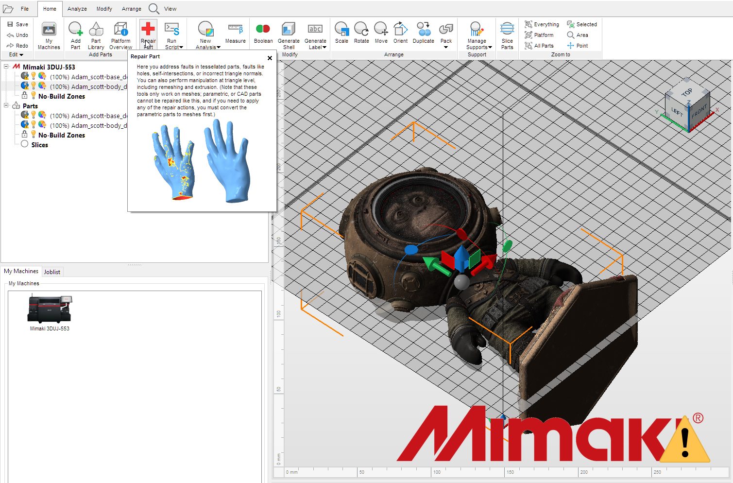
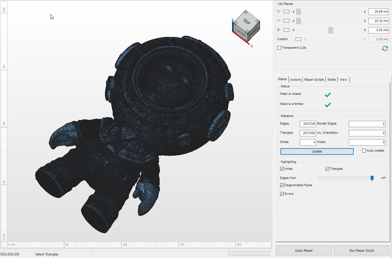
Select the body and click the Repair Part icon. This will cause the software to enter repair mode
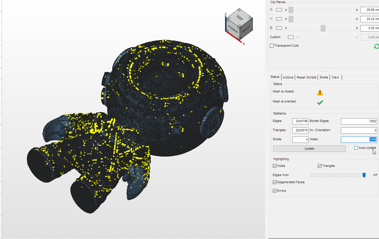
In the image here, the body has a lot of tiny holes and bad edges shown in yellow, mostly as a result of the export process from Blender. In this case, the automatic hole fixer and the edge fixer (stitch) will do the work without destroying the mesh. This is why it’s important to work with good topology.
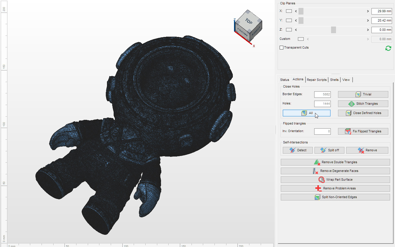
Go to the actions tab and click on the ‘Close Holes’/ ‘All’ icon. The software will fix the bad triangles and the yellow areas will turn blue; this means that these holes and edges have been fixed.
Other modeling tools can be used for more extensive repairs, by manually fixing certain problems. those extensive repairs require more edition time, make sure that the color and surfaces don't get destroyed in the process.
Go back to the Status tab and, after updating, the model will be error-free. Click on ‘Apply Repair’. You can choose to replace the file or keep the original part to compare and create a new file with the fixed version. Repeat the repair with the mesh of the base.
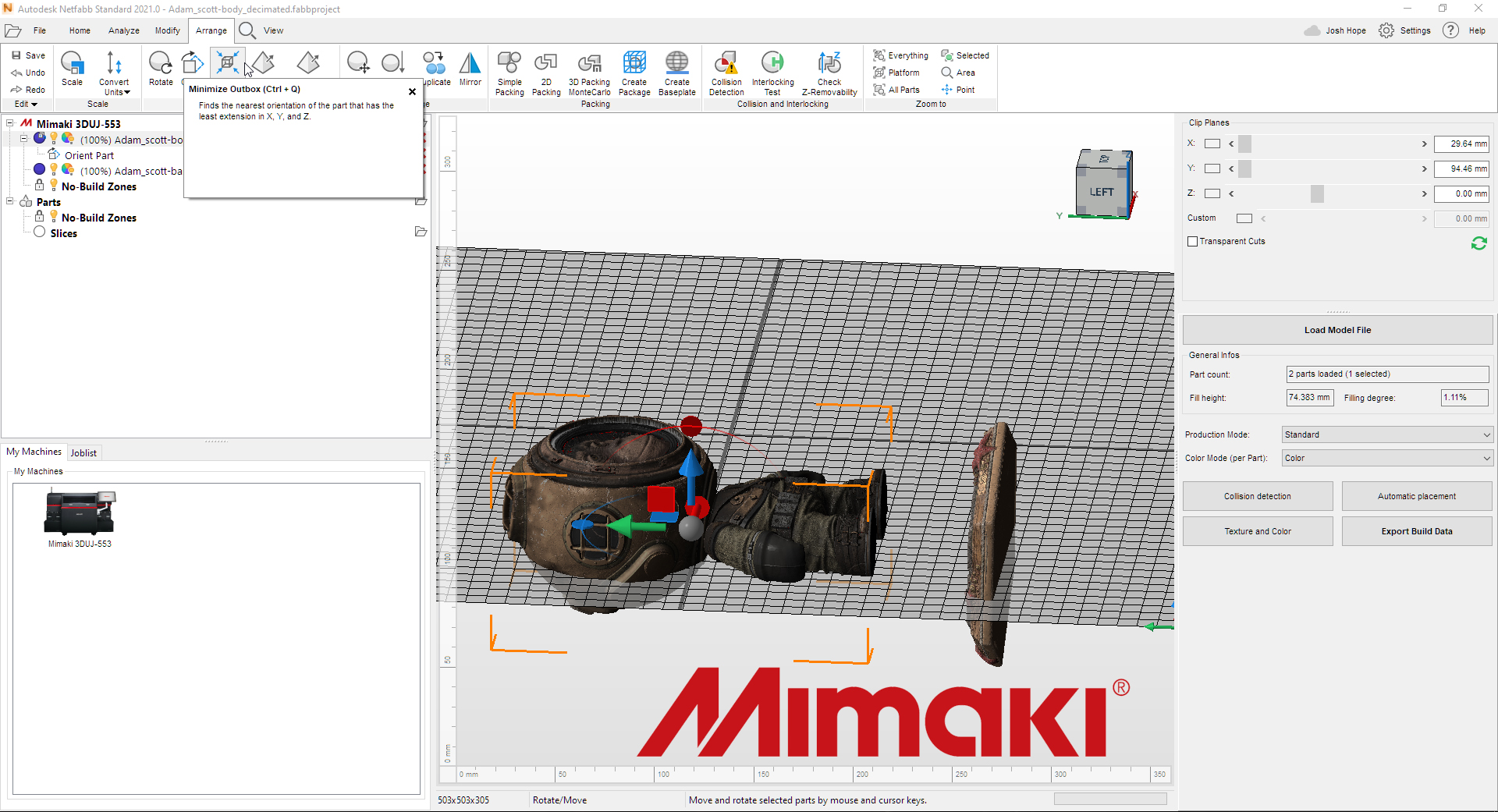
Orienting the part is mainly useful in order to save printing material, and to optimize printing times. The correct orientation depends on the 3D technology used. In Material Jet Manufacturing (MJM), the goal is to reduce the height in the Z axis, and to have as much surface contact as possible with the table.
Select the body and go to Arrange, then click on the Minimize Outbox icon.
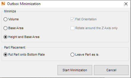
A dialog box will open; select the ‘Height and Base Area’ in the ‘Minimize’ section and ‘Put Part onto Bottom Plate’ in the ‘Part Placement’ section.
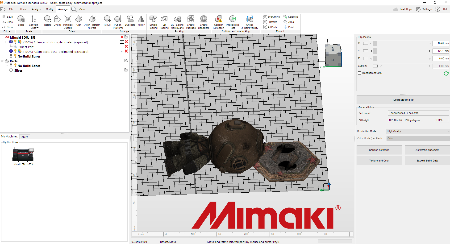
Repeat the operation with the Base mesh.
Once the parts are oriented, you can save the files to send externally via File/Export Part. You can create print jobs for the Mimaki 3DUJ-553 using the Export Build Data button.
Anything bigger than 4K for image resolution in Substance Painter is probably not necessary when 3D prining with color.
When working with displacement, height and normal textures, try experimenting with 16-bit color to get smoother transitions and crisper effects.
Be mindful with displacement and get the surfaces to maintain the same orientation, if possible.
For the final print file, the base color texture can be reduced from 4K to 2K; this will process faster.
One extra point: ideally, when working with a print service company, the company should have little to do other than verify the absence of potential problems with any files sent. In practice, however, it can be extremely helpful to maintain an ongoing dialog between designers and printers throughout the printing process – particularly with an emerging technology such as 3D printing it’s possible to run into unanticipated issues, and ongoing communication between designers and printers can be a great help in ensuring that final printed parts meet all expectations.